Lithium-ion battery is a secondary battery (rechargeable battery) that mainly relies on the intercalation and deintercalation of Li+ between two electrodes. With the continuous development of downstream industries such as new energy vehicles, the production scale of lithium-ion batteries is expanding. This article takes lithium cobalt oxide as an example to comprehensively explain the principle, formula and process flow of lithium-ion batteries, the performance and testing of lithium batteries, production precautions and design principles.
1. The principle, formula and process flow of lithium-ion batteries;
1. Working Principle
1. Positive electrode structure
LiCoO2 + conductive agent + binder (PVDF) + current collector (aluminum foil)
2. Negative electrode structure
Graphite + Conductive agent + Thickener (CMC) + Binder (SBR) + Current collector (Copper foil)
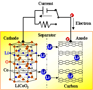
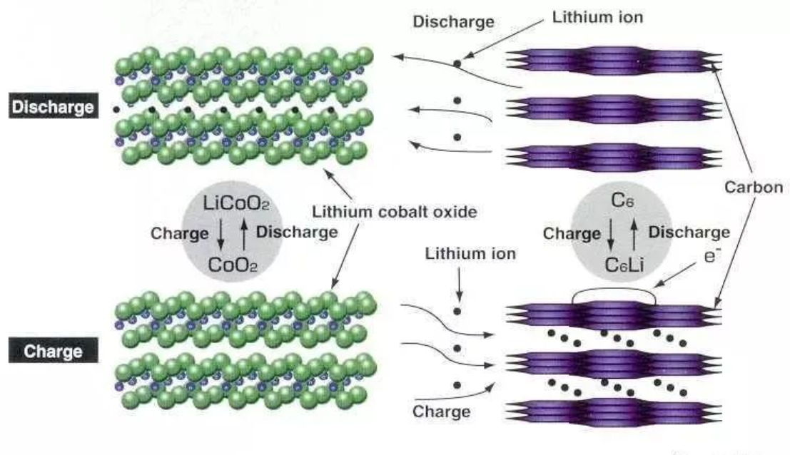
3. Working principle
3.1 Charging process
A power source charges the battery. At this time, the electrons e on the positive electrode run to the negative electrode through the external circuit, and the positive lithium ions Li+ "jump" into the electrolyte from the positive electrode, "crawl through" the winding holes on the diaphragm, and "swim" to the negative electrode to combine with the electrons that have already run over.
From a molecular level, it can be intuitively understood that over-discharge will cause the negative electrode carbon to release excessive lithium ions and cause its layer structure to collapse. Over-charging will force too many lithium ions into the negative electrode carbon structure, making some of the lithium ions unable to be released anymore.
Unsuitable temperature will trigger other chemical reactions inside the lithium-ion battery to generate compounds that we do not want to see, so a protective temperature-controlled diaphragm or electrolyte additive is installed between the positive and negative electrodes of many lithium-ion batteries. When the battery temperature rises to a certain level, the pores of the composite membrane close or the electrolyte denatures, the internal resistance of the battery increases until it is short-circuited, and the battery no longer heats up, ensuring that the battery charging temperature is normal.
2. Lithium battery formula and process flow
1. Positive and negative electrode formula
1.1 Positive electrode formula: LiCoO2+conductive agent+binder+current collector (aluminum foil)
LiCoO2(10μm): 96.0%
Conductive agent (Carbon ECP) 2.0%
Adhesive (PVDF 761) 2.0%
NMP (increases adhesion): weight ratio of solid matter is 8:15
a) The positive electrode viscosity is controlled at 6000cps (temperature 25°C);
b) The weight of NMP must be properly adjusted to meet the viscosity requirements;
c) Pay special attention to the effects of temperature and humidity on viscosity
Positive active material:
Lithium cobalt oxide: positive electrode active material, lithium ion source, to improve the lithium source for the battery. Non-polar material, irregular shape, particle size D50 is generally 6-8 μm, water content ≤ 0.2%, usually alkaline, pH value is about 10-11.
Lithium manganate: non-polar substance, irregular shape, particle size D50 is generally 5-7 μm, water content ≤0.2%, usually weakly alkaline, pH value is about 8.
Conductive agent: chain-like substance, water content < 1%, particle size is generally 1-5 μm. Superconducting carbon black with excellent conductivity is usually used, such as Ketjen Carbon ECP and ECP600JD. Its functions: improve the conductivity of positive electrode materials, compensate for the electronic conductivity of positive electrode active materials; increase the electrolyte absorption of positive electrode sheets, increase the reaction interface, and reduce polarization.
PVDF adhesive: non-polar substance, chain-like, molecular weight ranging from 300,000 to 3,000,000; molecular weight decreases and viscosity deteriorates after absorbing water. Used to bond lithium cobalt oxide, conductive agent and aluminum foil or aluminum mesh together. Common brands include Kynar761.
NMP: Weakly polar liquid, used to dissolve/swell PVDF and dilute slurry.
Current collector (positive electrode lead): made of aluminum foil or aluminum tape.
1.2 Negative electrode formula : graphite + conductive agent + thickener (CMC) + binder (SBR) + current collector (copper foil)Negative electrode material (graphite): 94.5%Conductive agent (Carbon ECP): 1.0% (Ketjen superconducting carbon black)Binder (SBR): 2.25% (SBR = styrene butadiene rubber latex)Thickener (CMC): 2.25% (CMC = sodium carboxymethyl cellulose)The weight ratio of water: solid matter is 1600:1417.5a) Negative electrode viscosity control 5000-6000cps (temperature 25 rotor 3)b) The water weight needs to be adjusted appropriately to meet the viscosity requirements;c) Pay special attention to the effects of temperature and humidity on viscosity2. Positive and negative mixingGraphite : Negative active material, the main substance that constitutes the negative electrode reaction; mainly divided into two categories: natural graphite and artificial graphite. Non-polar substances are easily contaminated by non-polar substances and easily dispersed in non-polar substances; they are not easy to absorb water and are not easy to disperse in water. Contaminated graphite is easy to re-agglomerate after being dispersed in water. The general particle size D50 is about 20μm. The particle shapes are diverse and mostly irregular, mainly spherical, flaky, fibrous, etc.
Conductive agent : Its functions are:a) Improve the conductivity of the negative electrode sheet and compensate for the electronic conductivity of the negative electrode active material.b) Improve reaction depth and utilization rate.c) Prevent the formation of dendrites.d) Use the liquid absorption capacity of conductive materials to improve the reaction interface and reduce polarization. (You can choose to add or not according to the distribution of graphite particles).Additives: reduce irreversible reactions, improve adhesion, increase slurry viscosity, and prevent slurry precipitation.Thickener/anti-settling agent (CMC): a high molecular weight compound that is easily soluble in water and polar solvents.Isopropyl alcohol: a weakly polar substance, which can reduce the polarity of the adhesive solution and improve the compatibility of graphite and the adhesive solution after addition; it has a strong defoaming effect; it can easily catalyze the network crosslinking of the adhesive and improve the bonding strength.Ethanol: A weakly polar substance, which can reduce the polarity of the adhesive solution and improve the compatibility of graphite and the adhesive solution after being added; it has a strong defoaming effect; it can easily catalyze the linear crosslinking of the adhesive and improve the bonding strength (the effects of isopropyl alcohol and ethanol are essentially the same, and the cost factor can be considered when choosing which one to add during mass production).Water-based adhesive (SBR) : Bond graphite, conductive agent, additives and copper foil or copper mesh together. Small molecule linear chain emulsion, easily soluble in water and polar solvents.Deionized water (or distilled water) : diluent, added in appropriate amount to change the fluidity of the slurry.Negative lead : Made of copper foil or nickel strip.Energy or surface energy, so it is an endothermic reaction, and the overall temperature decreases during stirring. If conditions permit, the stirring temperature should be appropriately increased to facilitate heat absorption, improve fluidity, and reduce the difficulty of dispersion.
5) If a vacuum degassing process is added during the stirring process to remove gas and promote solid-liquid adsorption, the effect will be better.
6) Dispersion principles, dispersion methods and related contents in positive electrode ingredients
2.2.3 Dilution:
Adjust the slurry to a suitable concentration for easy coating.
2.2.4 Material ball milling
1) Pour the negative electrode and KetjenblackECP into the material bucket and add the ball mill (dry material: grinding ball = 1:1.2) and perform ball milling on the roller bottle, and control the speed above 60rmp;
2) After 4 hours, separate the ball mill through sieve;
2.2.5 Operation steps
1) Heat purified water to 80°C and pour into a power mixer (2L)
2) Add CMC and stir for 60±2min; set the parameters of the power mixer: revolution at 25±2min, rotation at 15±2r/min;
3) Add SBR and deionized water and stir for 60±2min;
Power mixer parameter settings: revolution 30±2min, rotation 20±2r/min;
4) Add the negative electrode dry material in four equal batches, and add pure water at the same time, with an interval of 28-32 minutes between each addition; set the power mixer parameters: revolution at 20±2r/min, rotation at 15±2r/min;
5) After the fourth addition, high-speed stirring is performed at 30±2r/min for 480±10min;
Power mixer parameter settings: orbital revolution 30±2r/min, rotation 25±2r/min;
6) Vacuum mixing: Connect the power mixer to vacuum, maintain the vacuum degree at -0.09 to 0.10Mpa, and stir for 30±2min;
Power mixer parameter settings: revolution 10±2min, rotation 8±2r/min
7) Take 500 ml of slurry and measure the viscosity using a viscometer;
Test conditions: rotor number 5, speed 30 rpm, temperature range 25°C;
8) Take the negative electrode material out of the power mixer for grinding and sieving, and label it on the stainless steel basin. After handing it over to the slurry pulling equipment operator, it can flow into the slurry pulling process.
2.2.6 Notes
1) Complete and clean the equipment and working environment;
2) When operating the machine, pay attention to safety to avoid hitting your head.
Ingredients Notes:
üPrevent other impurities from mixing in;
üPrevent slurry from splashing;
ü The concentration (solid content) of the slurry should be adjusted gradually from high to low to avoid adding trouble;
ü Pay attention to scraping the sides and bottom during the mixing intervals to ensure uniform dispersion;
ü The slurry should not be left for a long time to avoid sedimentation or loss of uniformity;
ü The materials to be baked must be sealed and cooled before they can be added to avoid changes in the properties of the component materials;
üThe length of mixing time is mainly based on equipment performance and the amount of material added;
ü The stirring paddle should be replaced according to the difficulty of slurry dispersion. If it cannot be replaced, the speed can be adjusted from slow to fast to avoid damage to the equipment;
üScreen the slurry before discharging to remove large particles to prevent the belt from breaking during coating;
ü Strengthen the training of batching personnel to ensure that they have professional knowledge to avoid major disasters;
ü The key to batching is to disperse evenly and grasp the center. Other methods can be adjusted by yourself.
1. Parameters required for battery production2. Slurry pulling processa) Current collector sizePositive electrode (aluminum foil), intermittent coatingNegative electrode (copper foil), intermittent coatingb) Slurry weight requirements3. After positive electrode slurry drawing, the following steps are carried out:Cutting large pieces into small pieces Weighing (matching pieces) Baking and rolling pieces Welding of tabs and negative electrode slurry After that, the following processes are carried out:Cutting large pieces into small pieces, weighing pieces (matching pieces), baking, rolling pieces, and welding of tabs
Note : The vacuum degree of the vacuum system is -0.095-0.10Mpa; the protective gas is high-purity nitrogen, and the gas pressure is greater than 0.5MpaThe positive electrode tab is ultrasonically welded at the positive electrode sheet. The end of the aluminum strip is flush with the edge of the electrode sheet.Nickel bar size: 0.10×3.0×48mm. The nickel bar is spot welded directly with a spot welding machine. The number of spot welding points is required to be 8. The right side of the nickel bar is aligned with the right side of the negative electrode sheet, and the end of the nickel bar is flush with the edge of the electrode sheet.8 Diaphragm size : 0.025×44.0×790±5mm9 Needle winding width : 22.65±0.05mm10 Core pressing: After the battery is wound, first stick a 24mm wide transparent tape on the bottom of the battery cell, and then use a flattening machine to cold press twice.11 Requirements before battery cell is placed in the shell
Adhesive tape 1: 10.0×38.0±1.0mm, the adhesive tape is evenly distributed on both sides of the battery cell; Tape 2: 10.0×38.0±1.0mm, with the nickel strip in the center of the tape;Adhesive tape 3: 24.0×30.0±2.0mm, the adhesive tape is evenly distributed on both sides of the battery cell;The right side of the nickel bar is 7.0±1.0mm away from the right side of the battery cell.When installing the battery, use both hands to slowly install the battery into the battery case, and avoid scratching the battery.13 Negative electrode tab welding
The negative electrode nickel strip and the steel shell are welded with a spot welder to ensure welding strength and prohibit cold welding.During laser welding, the fixture should be carefully set up, and welding can only be carried out after the battery shell and the upper cover are well matched, and care should be taken to avoid welding deviation.15 Battery vacuum baking(1) The vacuum degree of the vacuum system is -0.095~-0.10MPa;
(2) The protective gas is high-purity nitrogen, and the gas pressure is > 0.5MPa;
(3) Vacuum and inject nitrogen once every hour16 Injection volume: 2.9±0.1gRelative humidity in the injection room: ≤30%, temperature: 20±5℃ Sealing tape: 6mm wide red tape. When sticking the tape, be sure to wipe off the electrolyte at the injection port. Use 2 rubber bands to fix the cotton at the injection port.a) Constant current charging: 40mA×4h; 80mA×6h
b) Full voltage inspection, batteries with voltage ≥3.90V are sealed, batteries with voltage <3.90V are sealed with 60mA constant current to 3.90~4.00V, and then steel balls are punched
c) Battery cleaning, the cleaning agent is acetic acid + alcohol(2) Continuation of the systemFollow the procedure to continue:
a) Constant current charging (400mA, 4.20V, 10min)
c) Constant current charging (400mA, 4.20V, 100 min)d
) Constant voltage charging (4.20V, 20 mA, 150 min)
f) Constant current discharge (750mA, 2.75V, 80 min)
h) Constant current charging (750mA, 3.80V, 90 min)
j) Constant voltage charging (3.80V, 20 mA, 150 min)(3) Detection and gradingThe batteries are classified into the following categories:After the battery is removed from the cabinet, the voltage is fully checked. Batteries with voltage less than 3.77V are recharged using the program:(1) Constant current charging (750mA, 3.80V, 10 min)(3) Constant current charging (750mA, 3.80V, 30 min)(4) Constant voltage charging (3.80V, 20 mA, 60min)After the batteries are removed from the cabinet and divided into different capacities, they are placed at room temperature for 20 days for re-inspection. The steps are as follows:a) Use a shaping machine to shape the battery;b) Fully inspect the battery thickness, voltage, and internal resistance. The classification method is as follows:2. Battery Manufacturing Process1. (Positive and negative electrodes) dry mixing → wet mixing → rolling paste on the conductive substrate → 3-step drying → winding → trimming (cut into a certain width) → rolling → winding (standby) dry mixing adopts ball milling, and the grinding balls are glass balls or zirconia ceramic balls;
Wet mixing uses a planetary powder mixer, whose blades are installed on 2-3 shafts respectively, for better mixing effect. The amount of solvent in wet mixing should be appropriate to form a suitable rheological state to obtain a smooth coating. The electrode paste should be rolled to ensure a certain viscosity. The paste is applied to both sides of the aluminum foil or copper foil, and the thickness of the coating depends on the model of the battery. Then it is dried through three heating zones in succession. NMP (or water) evaporates from the coating with the flow of hot air or dry nitrogen, and the solvent can be recycled. Rolling is to increase the density of the coating and make the electrode thickness meet the size of the battery assembly. The pressure in the rolling stage should be moderate to prevent the powder from scattering during winding.
Assembly process of cylindrical battery: put insulating bottom ring into cylinder → wind the battery cell into cylinder → insert the mandrel → weld the negative electrode collector to the steel cylinder → insert the insulating ring → roll the steel cylinder → vacuum drying → liquid injection → weld the combination cap (PTC element, etc.) to the positive electrode lead → seal → X-ray inspection → numbering → formation → circulation → aging.The assembly process of square batteries : insulated bottom into steel box → sheet-shaped combined battery cells into tube → negative electrode current collector welded to steel box → upper sealing gasket → positive electrode current collector welded to rod lead → combined cover (PTC element, etc.) welded to rotating lead → combined cover positioning → laser welding → vacuum drying → liquid injection → sealing → X-ray inspection → numbering → formation → circulation → aging.Assembly process description : Take cylindrical batteries as an example (the basic process of square batteries is the same). Before winding the core into the drum, use ultrasonic welding to weld aluminum strips (0.08-0.15 mm thick, 3 mm wide) and nickel strips (0.04-0.10 mm thick, 3 mm wide) to the designated positions of the positive and negative conductive substrates as current collectors and leads.Battery separators are generally composed of PE/PP2 layers or PP/PE/PP3 layers. The separators are heat treated at 120℃ to increase their barrier properties and improve their safety.The positive electrode, separator and negative electrode are stacked and wound into a tube . Since paste electrodes are used, the paste material must be well combined with the substrate to form a high-density electrode. In particular, powder loss must be prevented to prevent it from penetrating the separator and causing an internal short circuit in the battery.Before the wound battery cell is inserted into the steel cylinder, an insulating bottom is placed at the bottom of the steel cylinder to prevent internal short circuit of the battery. This is the same for general batteries.The electrolyte generally uses LiPF6 and non-aqueous organic solvents. Before vacuum injection, the battery must be vacuum dried for 24/h to remove water and moisture from the battery components to prevent LiPF6 from reacting with water to form HF and shortening its life.The battery is sealed by applying sealant, inserting gaskets, crimping and shrinking the cross section. The basic principle is the same as that of alkaline rechargeable batteries. After sealing, the battery is cleaned of oil and spilled electrolyte with a mixture of isopropyl alcohol and water, and then dried. Use an odor sensor or "sniffer" element to check for battery leakage.After the entire battery is assembled , the battery must be checked with X-rays to determine whether its internal structure is normal, and to check for irregular battery cells, cracks in the steel shell, solder joints, short circuits, etc., to exclude batteries with the above defects and ensure battery quality.The last step is formation. When the battery is charged for the first time, a protective film is formed on the anode, called the solid electrolyte interphase (SEI). It prevents the anode from reacting with the electrolyte and is a key factor in the safe operation, high capacity and long life of the battery. After several charge and discharge cycles, the battery is aged for 2-3 weeks, micro-short-circuited batteries are removed, and then capacity sorting and packaging are carried out to become a commodity. • The positive and negative active substances can remain stable in the electrolyte for a long time The current outstanding problems of electrolyte • Compatibility with positive and negative electrodes. • As the voltage increases, the electrolyte solution decomposes to produce gas, which increases the internal pressure and causes damage to the battery's air quality.And the antioxidant capacity of the solvent is lower when the battery operating temperature is increased. 4. Requirements for diaphragm • Has certain mechanical strength and bending resistance, and the ability to resist dendrite penetration • Good water absorption, pore size and porosity meet the requirements 5. Requirements for the enclosure • Has high mechanical strength and can withstand general impact • Ability to resist process corrosion


' fill='%23FFFFFF'%3E%3Crect x='249' y='126' width='1' height='1'%3E%3C/rect%3E%3C/g%3E%3C/g%3E%3C/svg%3E)


No comments:
Post a Comment